fullsquare
@fullsquare@awful.systems
- Comment on [deleted] 6 days ago:
World can survive without one small time youtuber
- Comment on What's the deal with using phonetic symbols here on Lemmy? 2 weeks ago:
If you don’t want to see weirdos you have picked wrong timewasting site
- Comment on LED lighting in the garage / shack 3 weeks ago:
LEDs themselves are quiet but some SMPSs generate RFI. You can find SMPS that is RF quiet, or since LED strips take so little power, you can make a tiny linear power supply for them, linear power supplies don’t have RF problems
- Comment on Realistically, what do people plan to do on the Moon and Mars that requires a permanent, or long term human presence there? 3 weeks ago:
Musk believes in a sort of secular mormonism except instead of magic he has money so he tries to eventually, after millenia to spread his progeny over the entire known universe
- Comment on Intuitive explanation for conductor diameter v. electrical wavelength? 3 weeks ago:
Moxon is very slightly shortened 2el yagi. That other thing is effectively weird phased array of two almost halfwave dipoles, and it’s both worse and bigger, and also harder to make because it requires capacitors for gamma match
- Comment on Intuitive explanation for conductor diameter v. electrical wavelength? 3 weeks ago:
(Current rabbit hole: Should a HB9CV’s boom be conductive and electrically bonded to its elements?)
Yes it has to be, that’s how you feed its two elements. Boom is at zero electrical potential and forms half of transmission line that goes to gamma matches of both parts of antenna, and you can attach it to perpendicular conductive mast, or extend it for mounting to mast (has to be perpendicular if mast is metal)
Personally, i’d go with 4el yagi if we’re talking portable operation, because boom length is such that you can make it out of plastic tube and hide elements in it when moving around
- Comment on Intuitive explanation for conductor diameter v. electrical wavelength? 4 weeks ago:
openhamprep explanation is wrong
When you consider a segment of wire, it has some inductance and capacitance in that small segment, and the wider it is, the lower inductance and higher capacitance are. In other words, both X_L and X_C go down as diameter increases. Electric field lines within antenna are mostly perpendicular to wire everywhere except on ends, where they spread in all directions, which means that there’s some residual capacitance there that needs to be charged each cycle. This is called end effect and the wider wire is, the more of it you get. In fact, the same aspect ratio (length/diameter) gets you the same end effect ratio each time, and it’s usually in range of 0.98-0.95. If there’s insulation, then insulation has lower velocity of propagation as it has higher permittivity than air, and it is in place with highest electric field intensity, and this can also shorten necessary wire length a couple %. The more insulation there is, the more shortened antenna becomes
But wait, there’s more. We can think of antenna as a lossy resonator, where R is Rrad which for halfwave dipole would be 72 ohms, + loss resistance which is smaller, and neither are changing fast with frequency. What is changing faster is X_L and X_C, and the wider wire is, the smaller both of them are, and this means that you can go further off frequency and still have acceptable SWR, i.e. antenna made with wider wire has more bandwidth. For HF this means using masts or wire cages instead of single wire, but for VHF this gets more practical
Rrad depends on physical antenna length, and if antenna is shortened, then how it was done, but for the range we’re here it won’t change much
you can consider antenna wire as a transmission line, but it will need to include ground as the other side of transmission line, and then impedance is dependent on wire diameter to height over ground ratio. it’s not very useful
- Comment on Can I do something with this? 1 month ago:
rtl-sdr uses the same chip as dvb-t tuners, but the everything else part is completely different
- Comment on If someone's injected with cancer cells, they develop cancer. Could at least part of the increase in cancer be to do with people getting cancer cells inside their bodies, similar to a viral outbreak? 1 month ago:
cancer is in large part an old people disease, if you avoided dying of cholera you’re more likely to die of something else. also now there’s a lot of people who were exposed to carcinogens decades back, and we got better at treating pr preventing some other common causes of death like stroke or heart disease
- Comment on A Finnish town is heating itself with 2,000 tonnes of crushed rock: its giant “sand battery” can cover almost a month of heating demand and has cut district heating emissions by 70% 1 month ago:
that’s no problem at all, systems like that are in use
- Comment on A Finnish town is heating itself with 2,000 tonnes of crushed rock: its giant “sand battery” can cover almost a month of heating demand and has cut district heating emissions by 70% 1 month ago:
It’s easier to freeze water than to cool rock borehole
- Comment on Amateur Radio Has Never Been More Affordable — So Why Do Some Things Seem So Expensive? 2 months ago:
there are photos of 16 different radios and a couple of antennas, but the one in thumbnail is Elecraft KH-1
- Comment on Amateur Radio Has Never Been More Affordable — So Why Do Some Things Seem So Expensive? 2 months ago:
It’s up for you to decide. On U/VHF you can talk to other people directly (locally) like on HF. But you can also do things that HF can’t provide, like talk through repeater (uncommon on HF), or to ISS, or through satellites (HF bounces from ionosphere) or do longer distance communications from mountaintops, or do image transmission or packet radio (HF has less bandwidth). On receive only you can also download NOAA weather satellite images. You can make your own repeater from two baofengs. HF gets affected by space weather, U/VHF is not, and we’re entering solar minimum. 6m will take you far further than 2m but it’s usually bundled with HF radios
On higher end there’s also moonbounce, but it’s not in the budget category
- Comment on Amateur Radio Has Never Been More Affordable — So Why Do Some Things Seem So Expensive? 2 months ago:
Depends on what you want to do. UHF/VHF handheld radio can be had for 20-30, uSDX or QMX type small low power HF radio is closer to 100. You’ll also need battery, antennas (perhaps tuner) and something to put data in and out (headphones and microphone or cw key or audio interface to laptop) (no idea if it’s good but people use it)
- Comment on 2 months ago:
this also happens with dc once voltage is high enough
- Comment on Which path would the electrical current take? 2 months ago:
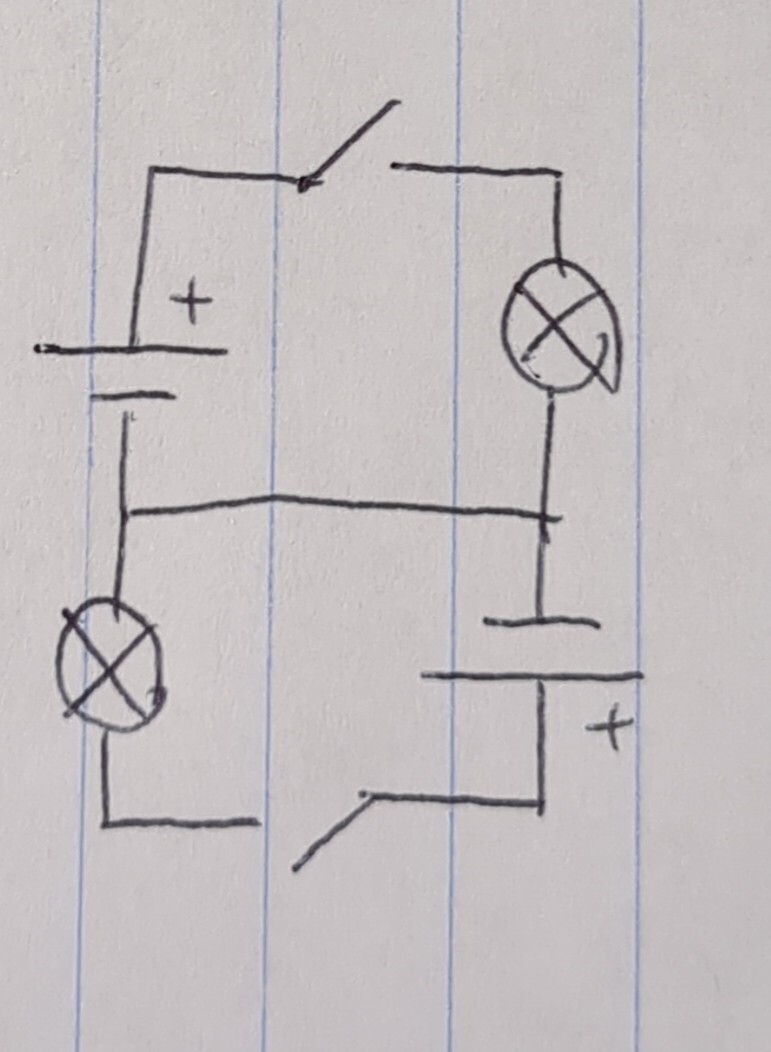
It’s easier to see that this circuit is rather symmetric when you redraw it
Then with both switches closed blue wire (the one in the middle) should only carry small current. If both halves are exactly the same it should be zero
In general when circuit doesn’t include nonlinear components (semiconductors most commonly) you can sum two valid solutions and you’ll get another valid solution. Note that when one switch is closed, current in blue wire goes one way and when the other is closed, in opposite way
- Comment on New clean energy comes out. *look inside* It’s just boiling water again… 2 months ago:
there are still coal powerplants around and any replacement is better. geothermal doesn’t work everywhere
- Comment on New clean energy comes out. *look inside* It’s just boiling water again… 2 months ago:
Coal ash (from some mines) contains so much uranium that if emissions like this were detected near NPP all hell would break loose, but nobody cares. Energy content of that uranium can be higher than what was released during coal combustion
- Comment on New clean energy comes out. *look inside* It’s just boiling water again… 2 months ago:
it replaces gas turbine with a fuel cell, which is a good couple % more efficient than CCGT. still under development. there is also another variant where hot offgas is generated under pressure and expanded directly. no steam, same effect
- Comment on The official HAM frequency designation is between 144mhz and 148mhz. So why are transceivers, even the monobanders, able to work on a much wider range? 2 months ago:
Could be. Amplifiers are a bit more complicated and there are many things that can limit bandwidth
- Comment on New clean energy comes out. *look inside* It’s just boiling water again… 2 months ago:
there is a power generation scheme that uses high temperature fuel cells. optimally it could run on hydrogen only, but because it runs hot, it is able to take almost any flammable gas, along with some steam, and it forms hydrogen internally, then oxidizes it. this alone generates bulk of electricity, but offgas is hot, so it goes to heat exchanger which boils water, which then turns steam turbine
- Comment on The official HAM frequency designation is between 144mhz and 148mhz. So why are transceivers, even the monobanders, able to work on a much wider range? 2 months ago:
If we consider groundplane antenna, which should be much better than anything that you can fit on a HT, it might be centered on 145MHz (region 2 band) and it’ll be good for 10MHz for 1:1.5 SWR (140-150) and 17MHz for 1:2 SWR (136.5-153.5) according to some random measurement, first that i found. Outside of these ranges SWR rises rapidly and if you tried to transmit on say 170MHz you might get SWR 1:5, perhaps 1:10 or worse if you’re unlucky. On receive this doesn’t matter too much because these nano- to microwatts of rx power would just bounce back harmlessly with the only effect being that apparent signal strength is lower. But if you tried to transmit then design currents or voltages would be exceeded and something will break, usually final stage of amplifier. This gets rarer than it used to be because some radios can measure SWR and will reduce power in such scenario. This also gets worse the higher transmitted power is
This happens because unlike on HF + 6m, on 2m and up ATUs are not a thing* and all antennas are expected to be matched. So you can use the same radio on GMRS or PMR or what have you and on 2m or 70cm band, but you have to change antennas between these uses. If you want to use all of these on one antenna, then there are special wideband designs like LPDA but this makes sense on a mast and not on handheld radio
* there are tuner designs that work on 2m and up, but you won’t find them in HT, there’s no point, they’re too big, too heavy and too expensive
- Comment on The official HAM frequency designation is between 144mhz and 148mhz. So why are transceivers, even the monobanders, able to work on a much wider range? 2 months ago:
Note that there’s 25% of fractional bandwidth in there and many antennas won’t work everywhere in that range (and also other elements like power dividers, diplexers etc if part of circuit)
- Comment on [FoAR] Foundations of Amateur Radio - CME, Wind, Flares, Flux and Geomagnetic Storms .. say what? #podcast 2 months ago:
related phenomenon. at calm solar surface, there’s only hydrogen and helium. these are excited thermally and can emit radiation, but the highest energy photon they can emit is ca 13eV and 52eV respectively. this is hard UV, and this is what is responsible for ionisation of ionosphere even during solar minimum, mostly F layer. but when solar flare forms, there are these giant loops of charged particles, and when charged particles change direction or brake, they release a lot of high energy radiation, that is xrays. xrays just go everywhere and this is partially what is responsible for extra ionisation of ionosphere during solar maximum, and this contributes more to E layer ionisation. when solar flare hits the earth, protons from it cause extra ionisation in D layer and this is why post-flare blackouts happen
- Comment on [FoAR] Foundations of Amateur Radio - CME, Wind, Flares, Flux and Geomagnetic Storms .. say what? #podcast 2 months ago:
there are also solar xrays, which also ionize ionosphere and are associated with CMEs (regular processes on surface of sun cannot make much xrays, it’s only when high energy particles are smashed back at the surface xrays are emitted. intense magnetic fields are needed for that)
- Comment on How to tune my ladder-line J-pole? 2 months ago:
Huh weird. There must be something evil in that pole, it might be a piece of metal or maybe it’s wet or rotting inside. I’d use plastic things to tie it, because natural fibers will remain wet some time after rain, that might degrade performance. (zipties or nylon fishing line or whatever preferably monofilament). I see that bottom is secured too, this is good because in wind antenna could flap around and would stop working if it’s too close to the pole. If twin lead is slightly twisted and under strain (half turn per 30cm or so) then it should flutter less in wind, but you’ve got it spliced and i’m not sure how that would work. This is likely fine as is
J-pole type antennas are effectively monoband. They might work on 3rd harmonic which would be here 70cm band, but most of signal in this case goes up and down that is it’s useless and the signal that goes out horizontally is 6db weaker than what it would be with J-pole for that band. So you can take more precise measurement by zooming in to 130-160MHz or even 140-150MHz, this way you’ll see how low does SWR go at band edges because now you can only see that there is minimum somewhere in the band. I don’t know how much your radio tolerates, but 1:1.5 is generally pretty good. On receive only it might be good also at other frequencies, but dedicated antenna would be likely better
I don’t know if you have calibrated your VNA with cable or not, you can use Smith chart if you do calibrate it with cable but without it, SWR shouldn’t change too hard with any reasonable length of cable (Smith chart rotates once per half wavelength of feedline). This is useful especially if you make your own antennas, but here it’s fine just to make sure that SWR is low
- Comment on Why are plug sockets region locked? 2 months ago:
50mm^2 for 125A, just under 8mm diameter solid copper rod if it was solid copper rod. but it’s stranded so it’s a bit bulkier than that, bundled five per cable so also squished into a wedge. it adds up to some 4cm in diameter
- Comment on Why are plug sockets region locked? 2 months ago:
split phase is 2-phase system but everyone else uses 3-phase distribution. in reality americans also use 3-phase distribution, this is where 207v 3-phase comes from (it’s 120v phase to neutral)
- Comment on Why are plug sockets region locked? 2 months ago:
the entire point of three phase circuit is that you can split it into single phase circuits without using too much wire. usually block will be wired so that 1/3 of flats is connected to one phase, but if you need to power big loads like ag tools or something like concrete mixer three phase supply can be done (415V these days, there’s upward shift in voltage)
- Comment on Why are plug sockets region locked? 2 months ago:
in EU there are really only two standards. for single phase loads up to 3.8kW, regular 16A plug is sufficient. above that, 3-phase 5-pin 32A plug (most common of them) is used which can deliver up to 23kW. there are common variants of 3-phase 5-pin plugs rated up to 125A that can deliver up to 89kW, and uncommon up to 800A variants that are also part of the standard, but it delivers up to 0.57MW and it’s a bit silly